|
|
|
Who's Online
There currently are 5925 guests online. |
|
Categories
|
|
Information
|
|
Featured Product
|
|
|
 |
|
|
There are currently no product reviews.
 ;
Excellent copies.
I will use "Owner Manual" again a second time.
 ;
Very good manual for Technics SL 303. Manuale molto utile.
;
About one hour after checkout, the manual was available for download. Clear reading and detailed. Thanks
;
Excellent transaction - clean document received - Thanks a lot
;
Manual is in German but complete. I needed this one to fix a long lasting problem with the internal PSU of the camera. Most of the capacitors begin to leak after a few years wich results in the inability to power on the camera. When you try to turn it on the power led flickers and the unit directly turns off. Thanks to this manual I was able to locate all bad cap's and to dis- and reassemble the camera without any problems.
DEH-P645,P56,P545,46,445,41
6.3 CHECKING THE GRATING AFTER CHANGING THE PICKUP UNIT
� Note : Unlike previous CD mechanism modules the grating angle of the PU unit cannot be adjusted after the PU unit is changed. The PU unit in the CD mechanism module is adjusted on the production line to match the CD mechanism module and is thus the best adjusted PU unit for the CD mechanism module. Changing the PU unit is thus best considered as a last resort. However, if the PU unit must be changed, the grating should be checked using the procedure below. � Purpose : To check that the grating is within an acceptable range. � Symptoms of Mal-adjustment : If the grating is off by a large amount symptoms such as being unable to close tracking, being unable to perform track search operations, or track searching taking a long time, may appear. � Method : � Measuring Equipment � Measuring Points � Disc � Mode
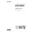
� Oscilloscope, Two L.P.F. � E, F, REFOUT � ABEX TCD-784 � TEST MODE
L.P.F. Xch E REFOUT 100kW 390pF Ych
Oscilloscope
F REFOUT
100kW 390pF L.P.F.
CONTROL UNIT
� Checking Procedure 1. In test mode, load the disc and switch the 5V regulator on. 2. Using the � and � buttons, move the PU unit to the innermost track. 3. Press key 3 to close focus, the display should read "91". Press key 2 to implement the tracking balance adjustment the display should now read "81". Press key 3 4 times. The display will change, returning to "81" on the fourth press. 4. As shown in the diagram above, monitor the LPF outputs using the oscilloscope and check that the phase difference is within 75° . Refer to the photographs supplied to determine the phase angle. 5. If the phase difference is determined to be greater than 75° try changing the PU unit to see if there is any improvement. If, after trying this a number of times, the grating angle does not become less than 75° then the mechanism should be judged to be at fault. � Note Because of eccentricity in the disc and a slight misalignment of the clamping center the grating waveform may be seen to "wobble" ( the phase difference changes as the disc rotates). The angle specified above indicates the average angle. � Hint Reloading the disc changes the clamp position and may decrease the "wobble".
79
|
|
|
> |
|